TEMPERATURE MEASUREMENT TECHNOLOGIES
Temperature transmitters: from the sensor to a reliable 4–20 mA signal
A temperature transmitter reads an RTD or a thermocouple and sends the temperature to the control system as a 4–20 mA current — often with HART or a fieldbus on top — over the same two wires that power it. That signal travels far without losing accuracy and resists electrical noise. Our catalogue includes the Klay Instruments TT-2000 and TT-4000, transmitters with a built-in Pt100, and the Delta Mobrey D72 Smart HART transmitter, which accepts both RTDs and thermocouples.
How a temperature transmitter works
The transmitter measures what the sensor gives — the resistance of an RTD, or the millivolts of a thermocouple together with its own cold junction temperature — and converts it to temperature. It then maps its range to a current: 4 mA at the bottom of the range and 20 mA at the top. Because zero temperature is 4 mA and not 0 mA, a broken wire shows up straight away as a current that should not exist.
Most transmitters are 2-wire: the same two wires carry the power from the control system and the signal back to it. The current is the same everywhere in the loop, so the resistance of a long cable does not change the reading, and a current signal resists electrical noise far better than millivolts. The TT-2000, for example, works from 12 to 36 V DC.
On top of the 4–20 mA, many transmitters speak HART, a digital signal that lets you configure the transmitter and read diagnostics from the control room or a handheld — the D72 uses it for diagnostics and recalibration without interrupting the process. Others use a fieldbus, such as Profibus PA on the TT-4000.
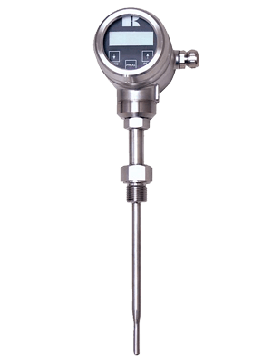
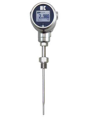
A transmitter can sit in the connection head of the sensor, on a DIN rail in a cabinet, or in its own field housing with a display. The Klay TT-2000 and TT-4000 combine a Pt100 and the transmitter in one instrument, with an accuracy of 0.1% — the TT-4000 optionally 0.075%. The accuracy of the whole measurement is that of the transmitter plus that of the sensor.
- The sensor — here an RTD element
- The sensor leads, here three, as far as the transmitter
- The transmitter electronics, which convert the reading into a current
- The 2-wire loop: it powers the transmitter and carries the 4–20 mA signal
- The bottom of the range gives 4 mA, the top 20 mA — never 0 mA, so a broken wire is detected
Where a temperature transmitter fits — and where it does not
A strong choice for
- Long distances between sensor and control system: a 4–20 mA loop is not affected by the resistance of the cable
- Electrically noisy plants, near motors and drives, where millivolt and resistance signals would pick up interference
- Thermocouples: the transmitter converts the weak millivolt signal close to the sensor, so ordinary copper cable can carry it from there
- Hazardous areas: the TT-2000 and TT-4000 carry ATEX and IECEx Ex ia approval
- Remote configuration and diagnostics over HART, or integration in a Profibus PA network
- A local reading at the point: the TT-4000 has a multilingual display with a bar graph
Think twice when
- The sensor sits next to a controller that accepts an RTD or thermocouple directly: a transmitter adds a component without adding much
- You only need a contact at a set temperature: a temperature switch is simpler
- The connection head gets too hot for the electronics: keep the transmitter within its ambient range — −20 to +70 °C for the TT-2000, −20 to +80 °C for the TT-4000 — with an extension neck or rail mounting
- You expect it to improve the sensor: the transmitter carries the reading faithfully, but the accuracy of the sensor still counts
How it compares with the other technologies
- RTDs (Pt100)−200…+600 °C
- Thermocouples−200…+1700 °C
- Temperature transmitters (the technology of this article)−200…+1700 °C *
- Temperature switches−50…+400 °C
Typical ranges, not a model commitment. RTD accuracy to IEC 60751 at 0 °C; thermocouple accuracy to IEC 60584, by type and class; for transmitters (*), the range is that of the sensor connected to them. We confirm the figures of each instrument for your application.
Installing a temperature transmitter
The first choice is where the transmitter goes: in the head, close to the sensor, so that only the robust current signal travels over the long cable; or on a rail in a cabinet, protected and easy to reach, with the sensor wired to it. Either way, the loop needs a power supply with enough voltage for the transmitter and the resistance of everything in the loop.
Then:
- Check the loop: the supply voltage must cover the minimum of the transmitter plus the voltage drop of the cable and the input — and, in hazardous areas, the limits of the barrier (for the TT-2000 in Ex, 12 to 26.5 V DC).
- With a thermocouple, connect it to the transmitter with the right extension cable; from the transmitter on, ordinary instrument cable is fine.
- Use screened cable and keep it away from power cables.
- Set the range to the process — a narrower range gives a finer resolution.
Temperature transmitters by industry
Temperature transmitters in our catalogue
The temperature transmitters in our catalogue, each with its own page and technical data.
Temperature transmitters: frequently asked questions
Ask about a temperature transmitter
Tell us the sensor (RTD or thermocouple, or whether you need the sensor too), the temperature range, the output (4–20 mA, HART, Profibus PA), the mounting and the area classification — and our engineers will suggest the right transmitter, with price and delivery time.