TEMPERATURE MEASUREMENT TECHNOLOGIES
Thermocouples: temperature measurement up to 1,700 °C
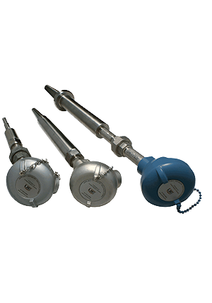
A thermocouple is made of two wires of different metals, joined at the tip. When the tip is hotter than the other end, the pair produces a small voltage that depends on the temperature difference. Simple, robust and able to work at very high temperatures — up to about 1,700 °C, depending on the type — the thermocouple is the usual choice for furnaces, kilns, flue gas and machines that vibrate. Our catalogue includes the industrial thermocouples of United Electric Controls.
How a thermocouple works
Join two wires of different metals at one end and heat that end: a small voltage appears between the free ends. This is the Seebeck effect, and the voltage depends on the temperature difference between the joined end — the hot junction — and the free ends. It is small: a type K thermocouple gives about 4.1 mV at 100 °C, with the free ends at 0 °C.
Because the voltage depends on a difference, the instrument must also know the temperature of the free ends, where the thermocouple wires meet its terminals — the reference, or cold, junction. A sensor at the terminals measures it, and the instrument adds it to the reading. This is called cold junction compensation.
Each pair of metals is a type with a letter, defined by IEC 60584. Type K (nickel-chromium / nickel-aluminium) is the most common general-purpose type, up to about 1,200 °C; type N is similar and more stable at high temperatures; types J and T suit lower temperatures; types R and S (platinum-rhodium / platinum) go up to about 1,600 °C, and type B up to about 1,700 °C.
IEC 60584 also defines tolerance classes. For type K, class 1 allows ±1.5 °C or ±0.4% of the temperature, whichever is greater, and class 2 ±2.5 °C or ±0.75%. At high temperatures the wires slowly change, so the reading can drift with time: thermocouples in hot service should be checked and replaced periodically.
- The hot junction of the two different wires (one drawn solid, one dashed)
- The heat at the measuring point
- The reference (cold) junction, with its own temperature sensor for cold junction compensation
- The voltage rises with the temperature difference, along a slight curve — a few millivolts
Where a thermocouple fits — and where it does not
A strong choice for
- Very high temperatures: furnaces, kilns, incinerators, heaters and flue gas — up to about 1,200 °C with types K and N, and higher with types R, S and B
- Machines with vibration or shock, such as engines, compressors and turbines: a welded junction in a mineral-insulated sheath has nothing fragile to break
- A fast response: a thin sheath or an exposed junction follows rapid temperature changes
- Small spaces, surfaces and thin probes, since the sensor can be made very thin
- A wide range with one sensor, and a simple, inexpensive construction
Think twice when
- You need accuracy better than the ±1.5 °C of a class 1 type K, J or N thermocouple: a Pt100 RTD (class A ±0.15 °C at 0 °C) is more accurate up to about 600 °C
- You need long-term stability at high temperatures without periodic checks: the wires drift with time
- The sensor is far from the instrument: the millivolt signal needs an extension cable of the same type and picks up electrical noise — fit a transmitter instead
- The installation mixes cable types or reverses the polarity: every joint must use the right thermocouple materials, or it adds an error
How it compares with the other technologies
- RTDs (Pt100)−200…+600 °C
- Thermocouples (the technology of this article)−200…+1700 °C
- Temperature transmitters−200…+1700 °C *
- Temperature switches−50…+400 °C
Typical ranges, not a model commitment. RTD accuracy to IEC 60751 at 0 °C; thermocouple accuracy to IEC 60584, by type and class; for transmitters (*), the range is that of the sensor connected to them. We confirm the figures of each instrument for your application.
Installing a thermocouple
The hot junction is at the tip, so the tip must sit where you want the temperature, deep enough that heat conducted along the sheath does not distort the reading. In furnaces and flue ducts the thermocouple usually sits in a protection tube of metal or ceramic, which keeps the hot, corrosive atmosphere away from the wires.
The weak signal also needs care on its way to the instrument:
- Match the thermocouple type in the sensor, the extension cable and the instrument or transmitter settings.
- Keep the signal cable away from power cables and drives, or fit a transmitter close to the sensor.
- Check thermocouples in hot service periodically, and replace them when they drift.
- Use a protection tube suited to the atmosphere — metal for most, ceramic for the hottest furnaces.
Thermocouples by industry
Thermocouples in our catalogue
The thermocouples in our catalogue, each with its own page and technical data.
Thermocouples: frequently asked questions
Ask about a thermocouple
Tell us the medium or atmosphere, the temperature range, the process connection and immersion length, the type if you know it, and the output you need — and our engineers will suggest the right thermocouple, with price and delivery time.