PRESSURE MEASUREMENT TECHNOLOGIES
Differential pressure transmitters: level, filters and flow from one difference
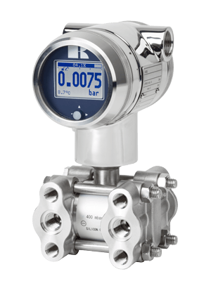
A differential pressure transmitter measures the difference between two pressures and sends it to the control system. That one measurement answers many questions: the level in a closed or pressurised tank, how clogged a filter is, the flow through an orifice plate, or a draft of a few millibar in a furnace. Our catalogue includes the Delta Mobrey D34 and D35 and the Klay Instruments DP-4000.
How a differential pressure transmitter works
The sensing cell has two isolating diaphragms, one on each side. The higher pressure acts on one, the lower pressure on the other, and a fill fluid carries both to a sensing element in the middle, which feels only their difference. The transmitter sends that difference as 4–20 mA, with HART on the D34 and the DP-4000, and Profibus PA on the DP-4000.
The line itself can be at a far higher pressure than the difference being measured — the static pressure. The D35 measures differences from −100 mbar to 70 bar at working pressures up to 420 bar; the DP-4000 measures spans from 10 mbar at static pressures up to 160 bar, or 250 bar as an option. Overpressure on one side only must stay within the rating of the instrument — 1 bar on the D34, which is made for very low pressures.
One difference, many measurements. With the high side at the bottom of a closed tank and the low side at the top, the transmitter measures only the liquid column. Across a filter, a rising difference shows that it is clogging. Across an orifice plate or another primary element, the flow is proportional to the square root of the difference, as ISO 5167 describes — a transmitter can take that root itself and send flow directly.
The DP-4000 is accurate to 0.075% of span, or 0.065% as an option, with a turndown up to 100:1; the D34 to ±0.1%. The DP-4000 offers diaphragms in Hastelloy C, tantalum or gold-plated steel, and the D35 is built with dual diaphragm seals for demanding media.
- The two pressures, pushing from opposite sides: the higher (dark) and the lower (orange)
- The fill fluid, which carries both pressures to the sensing element
- The sensing element (orange chip), which feels only the difference
- The 4–20 mA loop to the control system
- Through an orifice plate, the flow rises with the square root of the difference
Where a differential pressure transmitter fits — and where it does not
A strong choice for
- Level in closed or pressurised tanks, vessels and boiler drums, where the gas above the liquid has its own pressure
- Pressure drop across filters, strainers and heat exchangers — to clean or change them when needed, not by the calendar
- Flow of liquids, gases and steam through an orifice plate, a venturi or another primary element
- Very low pressures and drafts in furnaces, combustion air and ventilation — the D34 is made for draft and furnace measurements
- Small differences on lines at high static pressure, such as the D35 at working pressures up to 420 bar
- Corrosive, viscous or hot media, with diaphragm seals as on the D35
Think twice when
- You only need the pressure at one point: a pressure transmitter is cheaper, with one connection instead of two
- The difference may exceed the span of the instrument, such as a very high gauge pressure
- The impulse lines could freeze, crystallise or clog, and there is no heat tracing or diaphragm seal
- You need flow over a very wide range: with the square-root relation, a primary element covers about 1:10
How it compares with the other technologies
- Pressure transmitters25 mbar…2000 bar
- Differential pressure transmitters (the technology of this article)10 mbar…70 bar *
- Pressure switches10 mbar…400 bar
- Pressure gauges10 mbar…4000 bar
Typical ranges, not a model commitment, on a logarithmic scale. For differential pressure transmitters (*), the range is that of the difference; the static pressure of the line can be much higher. We confirm the figures of each instrument for your application.
Installing a differential pressure transmitter
Two connections mean two impulse lines, and the measurement is only as good as their match. Run both lines side by side, with the same slope and at the same temperature, so that whatever happens to one happens to the other, and connect them through a manifold.
Then:
- On liquids, mount the transmitter below the tappings; on gases, above them — as with a pressure transmitter.
- On a closed tank with condensing vapour, the low-pressure line fills with condensate: use a filled line or seals, and allow for it in the range.
- Heat-trace the lines, or use diaphragm seals, where the medium could freeze or crystallise.
- Follow the manifold sequence when putting the transmitter in and out of service, so that one side is never overpressured alone.
Differential pressure transmitters by industry
Differential pressure transmitters in our catalogue
The differential pressure transmitters in our catalogue, each with its own page and technical data.
Differential pressure transmitters: frequently asked questions
Ask about a differential pressure transmitter
Tell us the application (level, filter or flow), the medium, the differential range and the static pressure, the process temperature, the connection, the output and the area classification — and our engineers will suggest the right transmitter, with price and delivery time.